Author: Youngjin Kang Date: August 18, 2024
There are many ways of conceptualizing a system. In computer science, it is typical to picture it as a state machine. One of the main downsides of this approach, however, is the ensuing complexity.
A fairly small system with only a few number of possible states is pretty easy to model as a state machine; all we need to do is come up with a set of states (i.e. nodes in a graph), and a set of transitions between states (i.e. edges between the nodes). This lets us devise the entire system simply by drawing a state diagram.
A system with an enormous number of states, on the other hand, is not something which we are able to design in terms of a single state machine without pulling our hair off out of sheer confusion. While it is technically possible to formultae even an extremely complex system (such as a whole computer) as an FSM (Finite State Machine) in which the current state of the system is represented as one of the nodes in a graph, such a way of modeling the system is prohibitively convoluted.
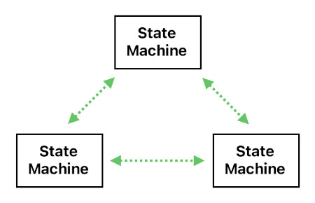
Therefore, it usually makes more sense to imagine a complex (non-trivial) system not as a single state machine, but as a collection of multiple state machines (i.e. modules), each of which keeps track of its own state. This design philosophy also aligns itself with the OOP (Object Oriented Programming) paradigm, where each object is a state machine with its own set of states (i.e. all possible permutations of the member variables) and state transitions (i.e. all possible ways in which the member variables can change their values).
Such a multitude of state machines, though, can operate as parts of one underlying system only if they are able to influence each other - that is, they must be able to communicate. If not, they will be a mere juxtaposition of completely isolated systems.
The question is, "What kind of communication"? There are innumerable ways of sharing information with one another, yet some of them are far more efficient than others. Thus, a wise designer of a system should be able to choose an optimal (or at least a nearly optimal) means of letting state machines affect each other's state.
In this article, I will showcase a new method of communication between state machines which I consider as fairly optimized for a wide variety of applications in system design, such as video games, cellular automata, circuit simulators, and many others.
Since I am personally more familiar with game development than any other area of engineering, it is probably appropriate for me to start with an example which takes place in a video game.
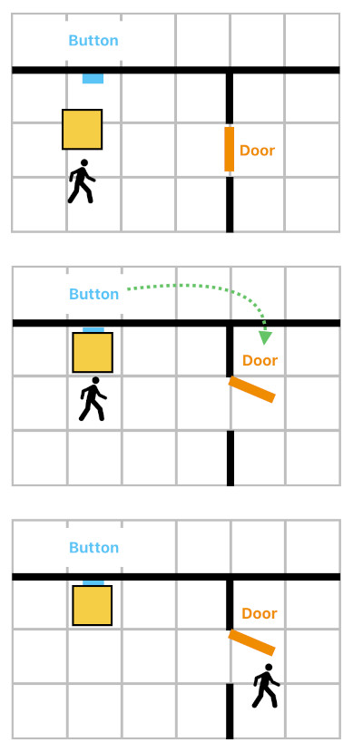
Suppose that there is a top-down game in which the player is going on an adventure in a maze-like world. There are walls preventing him from moving freely, so he is forced to use doors. Unfortunately, some of the doors are locked, which means that the player must figure out how to unlock them in order to get to the other side of the wall.
The image below is an example of a locked door. This door stays open only when the nearby button is being pressed, and immediately closes itself as soon as the button is released. So the only way for our player to cross the door is to first place a box right in front of the button to press it. Unless somebody moves it away, the box will continue pressing the button, and the player will be free to cross the door.
How shall we implement such a game mechanic? One of the most intuitive ways, obviously, is to model each individual object as a state machine. For instance, the door is a state machine with two states called "Closed" and "Open", and the button is a state machine with two states called "Released" and "Pressed".
The diagram below shows how the button "talks" to the door, so as to make the aforementioned rule work. Whenever the door is closed and the button is pressed, the button tells the door to open up. And whenever the door is open and the button is released, the button tells the door to close.
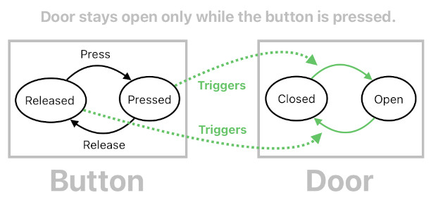
What we are witnessing here is a pair of state machines - the door and the button. Both of them have their own states and state transitions, and they run concurrently (i.e. both the door's state and button's state are active at the same time). Yet they are not disjoint from each other; the button's state influences the door's state, thereby forming a cause-and-effect relation.
We may refer to such a network of state machines as a "multi-state machine", since the whole thing behaves as though it is a state machine with multiple concurrent states.
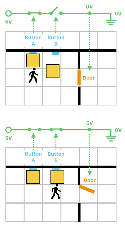
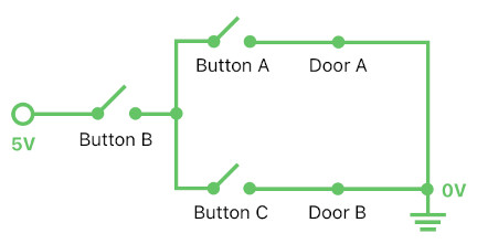
Let us take a look at a slightly more involved scenario. Suppose that there are two buttons called "button A" and "button B", and that there is a door which stays open only when both of these buttons are simultaneously being pressed (not just one of them, but both). This is an AND relation in boolean logic, and the image below shows an electric circuit analogy of such a logical operation. Here, the two buttons are analogous to two electrical switches which are connected in series. Only when both of them are pressed, the whole circuit becomes conductive and enables itself to activate (open) the door.
An engineer might be tempted to implement this using a logic gate (i.e. AND gate), which is a sound approach in a general computing environment in which binary logic operators (such as &&, ||) are some of the most primitive building blocks of expressions. The temptation gets even larger when the engineer is developing a game which is meant to be executed not on a personal computing device (e.g. PC or mobile), but on a piece of programmable hardware, such as FPGA (Field-Programmable Gate Array), wherein logic is being configured by establishing connections upon a vast 2D array of pre-embedded logic gates.
Outside of the realm of digital design, however, logic gates may not be the most appropriate elements to use. A video game, for example, is often filled with a myriad of wild mechanics which are not so easily explicable in terms of binary logic operators, such as dialogues, spatial reasoning (e.g. rush hour puzzles), various causal chains, and many others.
In order to encompass most (if not all) of all these non-boolean mechanics in our design protocol, therefore, we must come up with a framework which is more versatile than a mere assembly of binary logic elements. In my opinion, such a framework can easily be discovered when we stop thinking in terms of logic gates (e.g. AND, OR, NOT, etc) and begin to design the whole system using state machines and their transition rules only.
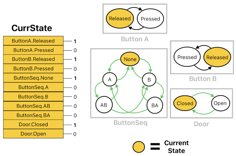
The diagram shown below is an example of how the aforementioend "AND" logic can be implementated by introducing an intermediatry state machine called "ButtonSeq" (i.e. "Button Sequence"), whose current state indicates the most recently ongoing sequence of button-presses. For instance,
(1) "None" means that neither button A nor button B is being pressed.
(2) "A" means that only button A is being pressed.
(3) "AB" means that button A was pressed first, button B was pressed second, and that they both have been being pressed since then.
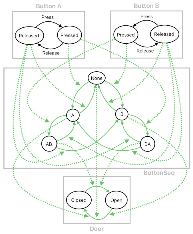
What you can see here is that both the "AB" and "BA" states trigger the door's transition from "Closed" to "Open". This means that, whenever button A and button B are both being pressed (regardless of the order in which they were initially pressed), the door is forced to be open.
In this example alone, we are already seeing an advantage of designing mechanics in terms of state machines instead of logic gates. Logical operators such as "AND", since they are commutative (i.e. they don't care about the order of the input parameters), are insufficient for handling cases in which the order of pressing these two buttons matters, and so forth. Imagine that, inside a game studio, the game designer comes over to the engineering team, gets mad, and says,
"Hey, the way you implemented my design was wrong. When I said that pressing button A and button B should open up the door, what I meant was that pressing button A AND THEN pressing button B should open up the door. I never said that pressing them the other way around should give the same result. What you guys made is clearly a bug. The entire level won't make any sense at all if you do not fix this immediately!"
Try making the requested adjustment by rearranging logic gates; it is fairly complicated to do so. If you configure things in terms of state machines, on the other hand, you will have an easier life because state machines are much more malleable than logic gates.
But of course, I can totally feel the sentiment that the above example somehow appears to "overcomplicate" a fairly simple piece of logic by not leveraging built-in logical operators. However, there is an enormous benefit in trying to formulate everything solely in terms of state machines; it is what I would call "structural uniformity".
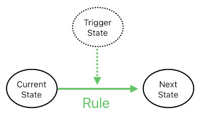
In the model we have been seeing so far, there has really been only a single type of semantic building blocks - state transition rules. Every one of these rules, without an exception, can be interpreted as a mapping of two states (i.e. "current state" and "trigger state") into another state (i.e. "next state"). In case of the state "AB" triggering the door to open, for instance, we can say that it is due to a rule in which "current state" is "Closed", "trigger state" is "AB" (because "AB" is the thing that triggers the door to open), and "next state" is "Open".
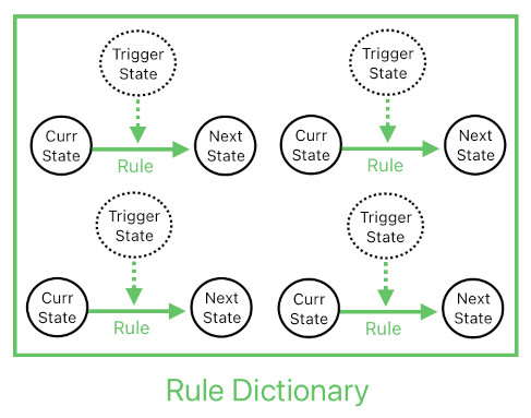
And if we gather all such rules in one place called "rule dictionary", we may claim that this dictionary alone fully describes the behavior of the whole system. This kind of simplicity is extremely helpful especially if we are aiming to implement it as a custom electronic module (in the form of an ASIC (Application-Specific Integrated Circuit), etc); less variety in the data structure means less complexity in the hardware.
The most challenging part is the implementation of the rules. It really depends on the hardware, but let us begin with the assumption that we are developing an application for a general-purpose computer (e.g. PC or mobile). The most brute-force approach is to execute the rules as a bunch of conditional statements, like the ones displayed below.
if (ButtonSeq.CurrState == "None" && ButtonA.CurrState == "Pressed")
    ButtonSeq.NextState = "A";
if (ButtonSeq.CurrState == "A" && ButtonA.CurrState == "Released")
    ButtonSeq.NextState = "None";
if (ButtonSeq.CurrState == "A" && ButtonB.CurrState == "Pressed")
    ButtonSeq.NextState = "AB";
if (ButtonSeq.CurrState == "AB" && ButtonA.CurrState == "Released")
    ButtonSeq.NextState = "B";
if (ButtonSeq.CurrState == "AB" && ButtonB.CurrState == "Released")
    ButtonSeq.NextState = "A";
...
if (ButtonSeq.CurrState == "AB" && Door.CurrState == "Closed")
    Door.NextState = "Open";
if (ButtonSeq.CurrState == "BA" && Door.CurrState == "Closed")
    Door.NextState = "Open";
if (ButtonSeq.CurrState == "None" && Door.CurrState == "Open")
    Door.NextState = "Closed";
if (ButtonSeq.CurrState == "A" && Door.CurrState == "Open")
    Door.NextState = "Closed";
if (ButtonSeq.CurrState == "B" && Door.CurrState == "Open")
    Door.NextState = "Closed";
It is not difficult to interpret the meaning of what is going on here. If ButtonSeq's state is "None" and ButtonA's state is "Pressed", ButtonSeq's state must change into "A", and so on. Each IF statement here is an individual state transition rule.
Of course, this is not the best way of implementing the rules. It is both hard-coded (which means it is not data-driven) and inefficient (because it introduces a long sequence of statements that the program needs to visit), so obviously we need a better approach.
A better (although not the best) way is to define the rules as entries in a nested dictionary which, in C# programming language, could be written as:
Dictionary<CurrStateOwner,
    Dictionary<CurrStateName,
        Dictionary<TriggerStateOwner,
            Dictionary<TriggerStateName,
                NextState>>>> RuleDictionary;
"CurrStateOwner" is the state machine whose "current state" is to be examined, and "TriggerStateOwner" is the state machine whose "trigger state" is to be examined. The rule dictionary is the data structure which maps these two states (i.e. "current state" and "trigger state") to the desired future state of "CurrStateOwner".
If we represent the rule dictionary of the previous two-button scenario in JSON format, it will be written as:
"RuleDictionary": {
    "ButtonSeq": {
        "None": {
            "ButtonA": {
                "Pressed": "A"
            },
            "ButtonB": {
                "Pressed": "B"
            }
        },
        "A": {
            "ButtonA": {
                "Released": "None"
            },
            "ButtonB": {
                "Pressed": "AB"
            }
        },
        "AB": {
            "ButtonA": {
                "Released": "B"
            },
            "ButtonB": {
                "Released": "A"
            }
        },
        ...
    },
    "Door": {
        "Closed": {
            "ButtonSeq": {
                "AB": "Open"
            },
            "ButtonSeq": {
                "BA": "Open"
            }
        },
        "Open": {
            "ButtonSeq": {
                "None": "Closed"
            },
            "ButtonSeq": {
                "A": "Closed"
            },
            "ButtonSeq": {
                "B": "Closed"
            }
        }
    }
}
While a nested dictionary is a pretty complicated and computationally inefficient data structure, one of its upsides is that it is extremely easy to use. Whenever the program happens to run the update loop of the "ButtonSeq" object, for instance, all it has to do is access the "ButtonSeq" entry of "RuleDictionary" to look up all the rules which belong to the "ButtonSeq" object. And within that "ButtonSeq" entry, all it has to do is access the inner entry which corresponds to the current state of the "ButtonSeq" object to look up all "trigger states" which may potentially determine the object's future state.
This makes a nested dictionary a great choice for quick data access. A more optimal means of implementing this dictionary is to come up with a number of relational data tables (like in SQL) and chain them together by means of primary/secondary keys, etc.
Syntactic redundancy, though, is going to ensue if we construct all the rules on a case-by-case manner. Imagine that there are 100 doors inside the game, each of which opens up only when a unique pair of buttons are simultaneously being pressed. There are numerous buttons (at least 50 or so), from which 100 such unique combinations are to be made for those doors. Indeed, we do not want to manually type all the rules for a hundred "ButtonSeq" objects. Fortunately, we know that we can abstract out the logic of "ButtonSeq" (i.e. AND operator) and turn it into a template which can be replicated as many times as we want.
In order for this to happen, we must first turn all the relevant states and their transitions into generic, parameterizable entities, like the ones shown below.
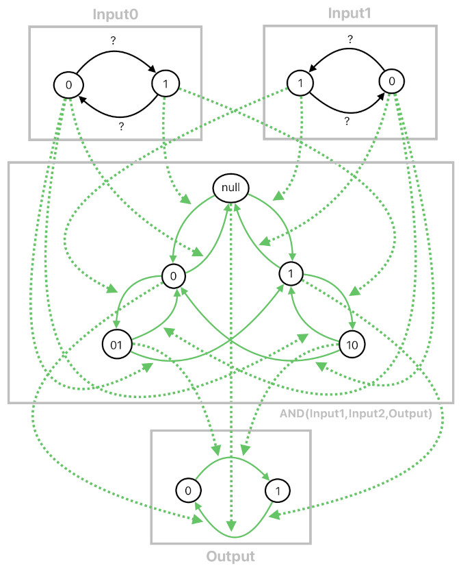
The idea is that, once they are all parameterized, we will be able to write a function which automatically creates a set of rules based on the given parameters. Such a function works as a template for generating rules, and is demonstrated in the Javascript code below:
const buttonA = {
    name: "buttonA",
    states: {
        "0": "Released",
        "1": "Pressed",
    },
};
const buttonB = {
    name: "buttonB",
    states: {
        "0": "Released",
        "1": "Pressed",
    },
};
const door = {
    name: "door",
    states: {
        "0": "Closed",
        "1": "Open",
    },
};


function AND(output, input0, input1)
{
    return `{
        "AND(${output.name}, ${input0.name}, ${input1.name})": {
            "null": {
                "${input0.name}": {
                    "${input0.states["1"]}": "0"
                },
                "${input1.name}": {
                    "${input1.states["1"]}": "1"
                },
            },
            "0": {
                "${input0.name}": {
                    "${input0.states["0"]}": "null"
                },
                "${input1.name}": {
                    "${input1.states["1"]}": "01"
                },
            },
            "01": {
                "${input0.name}": {
                    "${input0.states["0"]}": "1"
                },
                "${input1.name}": {
                    "${input1.states["0"]}": "0"
                },
            },
            ...
        },
        "${output.name}": {
            "${output.states["0"]}": {
                "AND(${output.name}, ${input0.name}, ${input1.name})": {
                    "01": "${output.states["1"]}"
                },
                "AND(${output.name}, ${input0.name}, ${input1.name})": {
                    "10": "${output.states["1"]}"
                },
            },
            "${output.states["1"]}": {
                "AND(${output.name}, ${input0.name}, ${input1.name})": {
                    "null": "${output.states["0"]}"
                },
                "AND(${output.name}, ${input0.name}, ${input1.name})": {
                    "0": "${output.states["0"]}"
                },
                "AND(${output.name}, ${input0.name}, ${input1.name})": {
                    "1": "${output.states["0"]}"
                },
            }
        }
    }`;
}


const rule_door = AND(door, buttonA, buttonB);
Here, the code just genereated the two-button rule (i.e. "Both button A and B must be pressed in order to open the door") by calling the "AND" function, which took the door as the operator's output parameter and the two buttons (A and B) as the operator's two input parameters.
Leveraging this function-based rule instantiator, the developer is able to quickly come up with a wide spectrum of complex rules simply by calling functions. For example, take a look at the scenario below, expressed in the form of an electric circuit. It tells us that there are two doors (A and B) and three buttons (A, B, and C); door A opens up only when button A and B are both being pressed, whereas door B opens up only when button B and C are both being pressed.
By calling the "AND" function twice, each time with a unique combination of arguments, one can easily create two sets of rules which are different yet share the same type of logic (i.e. AND operator). These two sets of rules, when combined as a whole, will fully depict the above scenario. The following code shows us how to do it.
const rules_doorA = AND(doorA, buttonA, buttonB);
const rules_doorB = AND(doorB, buttonB, buttonC);
const ruleDictionary = `{
${rules_doorA},
${rules_doorB}
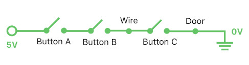
}`;Here is a slightly trickier example. What if there is a door which opens up only when all 3 of the buttons are being pressed, not just 2? This may baffle the designer a bit because the AND function only takes two inputs. This problem, though, is not hard to solve. All we need is an intermediary object (i.e. "wire") whose state is the result of applying the AND function to the first two buttons (A and B). This intermediary object, then, can be fed as an input parameter to another AND function along with the third button (C). The result of this AND function will be equivalent to the result of applying the AND operator to all three buttons (A, B, and C).
And the snippet below is the code implementation of what I just mentioned.
const wire = {
    name: "wire",
    states: {
        "0": "LowVoltage",
        "1": "HighVoltage",
    },
};


const rules_wire = AND(wire, buttonA, buttonB);
const rules_door = AND(doorB, wire, buttonC);


const ruleDictionary = `{
    ${rules_wire},
    ${rules_door}
}`;
Such a dynamic rule-generation script, as those of you with expertise in embedded systems may have noticed, closely resembles a hardware description language such as Verilog, since it is composed of a set of declarative statements which tell us the input-output relations between modules.
One may question the feasibility of this multi-state design scheme by saying, "What if the system accidentally triggers an undesirable race condition? For instance, in your second example, I noticed that it is possible to cause a race condition when ButtonSeq's current state is 'None' and both button A and B are pressed at the same exact time. What should ButtonSeq's next state be - A, or B? This kind of ambiguity makes me question the legitimacy of what you are expounding here."
In a parallel or concurrent (e.g. multi-threaded) environment, such edge cases will be detrimental to the system if they are not being handled properly. They may even cause two or more mutually exclusive states to be simultaneously active! I will deal with this problem near the end of this article (i.e. in the "Race Conditions in Parallel Processing" section).
If the system is simply running on a single-threaded environment, though, we have nothing to worry about. When the system's update loop runs the update procedure of one of the state machines, it will simply scan the rule dictionary from top to bottom and apply the first rule which happens to trigger the state to change. If the rule which makes ButtonSeq respond to button A is listed BEFORE the rule which makes ButtonSeq respond to button B, simultaneously pressing both button A and B will make ButtonSeq respond to button A only. No fatal error will arise, and no one but an over-enthusiastic QA will say anything about it.
The JSON representation of the rule dictionary, which I have demonstrated above, is a bit too inefficient both in terms of memory and speed. Thus, it is desirable to format the dictionary in a more compact manner.
There are a number of things we ought to do to make it happen. First, we should reference each individual state with a binary code instead of a string of characters (as shown in the table below). This greatly reduces the amount of data needed for referencing the states. Furthermore, it helps us significantly speed up the dictionary's lookup process because a numerical value can directly be used as an index in the hash table (whereas a string requires the application to compute its hash code first).
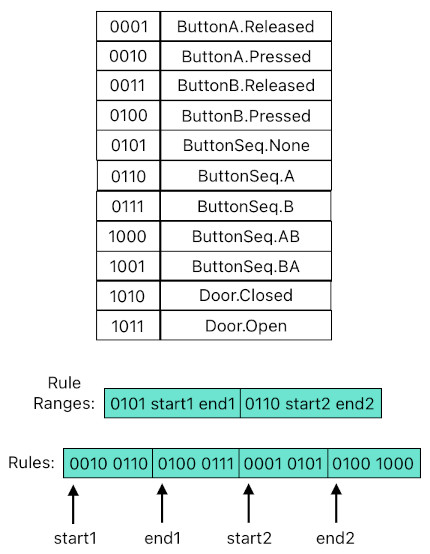
Secondly, we can even get rid of the nested dictionary data structure altogether if we express all the rules using two binary sequences (illustrated in the picture above), which may be referred to as "Rule Ranges" and "Rules", respectively.
The "Rule Ranges" sequence lists all the states of the system and their corresponding ranges in the "Rules" sequence (specified in terms of memory addresses). The "Rules" sequence lists all the rules which correspond to the given CurrState, each of which is denoted by the (TriggerState, NextState) pair.
When the system updates a state machine whose current state is 0101, for instance, it first looks up the range which corresponds to the entry 0101 in the "Rule Ranges" sequence (which corresponds to the range [start1, end1]). It then jumps into the "Rules" sequence, scans the entries in the range [start1, end1], and checks to see if the state 0010 or 0100 is currently active (Note: A state is "active" if it is the current state of one of the state machines). If 0010 is active, the program will change the current state of the machine from 0101 to 0110. If 0100 is active instead, the program will change the current state of the machine from 0101 to 0111.
Such raw-data representation of rules helps us minimize the size of its storage space, minimize the frequency of cache-miss (because more compactness of data means more data can be packed into the cache), and prevent potential incompatibility between ways in which different computing envirionments (e.g. operating systems) tend to handle data (because raw binary data does not make assumptions on how the environment will interpret it; the "rules engine" will simply interpret the data based upon its own custom way, regardless of on which platform it is running).
Versatility and compactness are not the only advantages of the multi-state model I have shown so far. Another major advantage of it is its ability to run on a parallel computing environment, given a custom hardware module.
In order to explain what sort of hardware it is, I must first introduce a hypothetical electronic component called "state activation indicator". It is a 1-bit memory storage (similar to a D Flip-Flop) which tells us whether each state is active or not. So, for example, if there is a state activation indicator which indicates the activation status of the door's "Closed" state, we say that the door's current state is "Closed" if and only if the indicator's output bit is currently 1.
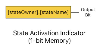
This means that the "current state" of the whole system, which is really the ensemble of all the current states of its constituent state machines, is a binary string of length N containing M number of 1s (where 'N' is the total number of all possible states of all the state machines, and 'M' is the number of the state machines themselves). The figure below demonstrates how this data representation works.
The system's current state can be characterized by an array of state activation indicators. Similarly, the system's next state (i.e. pending future state which is to be assigned back to the current state by the end of the application's clock cycle), too, can be characterized by an array of state activation indicators.
The image below is the hardware implementation that is necessary for the parallel multi-state machine to work. Between the two bit arrays which respectively represent the system's current state and next state, there is a two-dimensional grid of wire intersections, formed by both horizontally and vertically oriented electrical wires (i.e. conductors) which are placed at regular intervals. Each black dot denotes connection between the two intersecting wires (which means that if the value of one of the wires is 1, the value of the other wire will be 1 as well), and each green dot refers to the presence of an AND logic gate between the two intersecting wires. The result of this logic gate gets communicated through the green line.
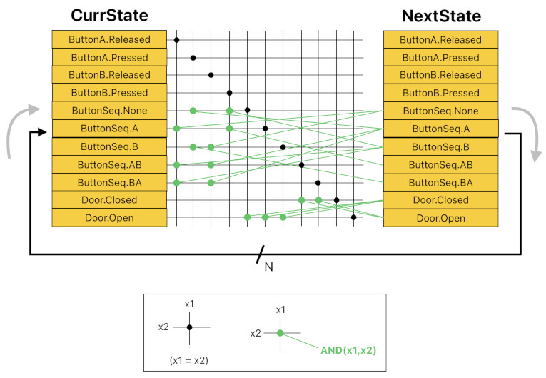
Here, each green dot (AND logic gate) corresponds to a state transition rule; it takes a "current state" and a "trigger state" as a pair of inputs, and yields the next state as the output. Imagine the green parts of the image above as the ones which are dynamically configured on a programmable hardware module (by means of tri-state buffers, transisters, etc), while the black parts are static and cannot be modified. Installing a rule dictionary, thus, is the same thing as establishing a bunch of green wirings between the grid's intersection points and their corresponding next-state memory input ports.
Once the wiring process is done, all we need to do is set the initial state of the system by pre-configuring the bits of CurrState and then starting the clock to initiate the cyclic flow of signals between CurrState and NextState. This will let the system update all of its states in parallel, without requiring the CPU to visit every individual state machine and update it sequentially.
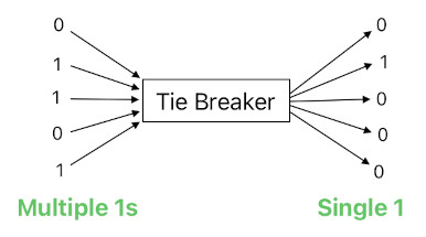
The aforementioned parallel implementation, though, is prone to introduce race conditions which may inadvertently make a state machine carry two or more concurrent states (which is inappropriate for a state machine). Therefore, we must add some kind of "postprocessing" stage to the end of the state transition cycle to resolve race conditions. For such a purpose, let me introduce yet another hypothetical module called "tie-breaker". It is an electronic component which takes a bit sequence as an input, leaves only a single "1" in it (if there are multiple of them), and returns the resulting sequence as the output.
Then, when the system's clock cycle (update loop) ends and its NextState is to be transferred back to CurrState, the system will need to feed each group of states in NextState (corresponding to each individual state machine) to a tie-breaker and assign its result to the respective group in CurrState, instead of simply copying the bits from NextState to CurrState directly. It is demonstrated in the image below.
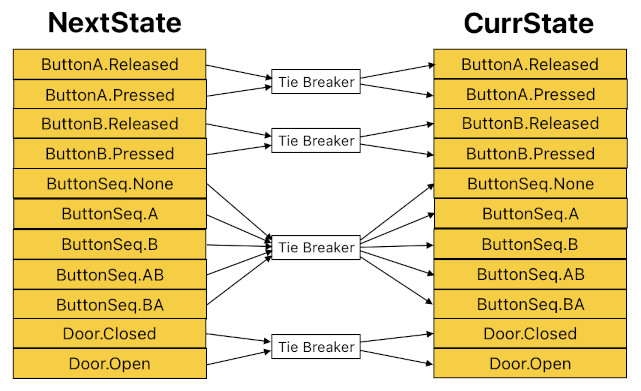
This is how the system can prevent any potential race conditions; each tie-breaker ensures that each state machine contains only ONE current state.
Previous Page Next Page© 2019-2026 ThingsPool. All rights reserved.
Privacy Policy Terms of Service